|
CUSHCRAFT 商用天線系列
ISM 12dBi
全向性高增益基地天線
要增長 2.4MHz 無線電網路卡的通訊距離的手段有三個途徑,
一是增加天線的高度, 二是採用低損失的高頻電纜線,
第三就是使用高增益的天線了
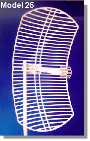
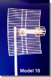
這裡備用超過 20dBi 的指向性碟型天線,
在無阻礙下以國內現行的 Z-COM 與 AONet 的無線電網路設備實測,
有超過 30 公里以上的表現.
這將是無線電區域網路架設業者的最佳解決方案.

上面這兩款天線是潤泰銷售最佳的天線, 我們特別將規格列示於下:
天線 |
饋電線 |
| Band Width |
2.4~2.5 GHz |
2.4~2.5 GHz |
Length: |
20ft. (4m) |
30ft. (10m) |
| Gain |
18 dBi |
16 dBi |
Cable Loss: |
1.66 dB |
2.18 dB |
| VSWR |
1.5:1 |
1.5:1 |
Assembly loss: |
2.16 dB |
3.305 dB |
| Beam Width |
17° |
E 30°H 65° |
Connector: |
N(M) - SMA(M/R) |
N(M) - N(F) |
| Weigh |
1.82 Kg per unit |
< 1 lb.per unit |
Note: |
|
with a 1 ft jumper
N(M) - SMA(M/R) |
| Size |
14.4x14.4x0.6 in |
22x2 in |
規格
N(M) : N 型公接頭
N(F) : N 型母接頭
SMA(M/R) : SMA 型接公頭母針
(reverse polarity)
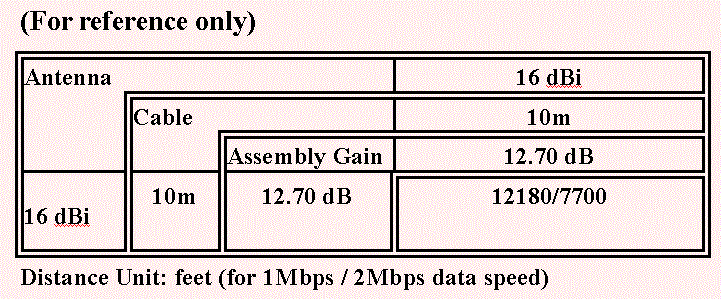
天線與距離的關係
Site Preparation
- First, choose two points which are line-of-sight. It
means that there is no obstructers such as buildings, hills, trees, power lines, etc. in
between.
- The point to install the antenna should be on the roof
or at least 10 meters high.
- For the safety’s sake, a lightning protection should be setup to provide a path to
the ground for the lightning’s
energy. The design of lightning protection function should protect not only the antenna
but also the users and equipment of the whole system.
- Also, a low impedance grounding should be made to
provide an energy sink for the lightning energy and static electricity.
Regulations
- In some countries, it is necessary to apply a license for
using transceivers.
- The maximum output power of transmitter is regulated and
varied by countries. End users should be responsible for operating it at or below the
level. (FCC in USA limits the effective isotropic radiated power to 36 dBm, and ETSI in
Europe limits that to 20 dBm)
- The antenna installer or end users should obey the relative
local regulations of antenna installation, lightning production and grounding.
Installation Guide
- Setup a supporter for antenna mounting kit.
- Using the mounting kit to fix the antenna to the supporter.
Be sure not to drive the screw too tight for adjustment.
- Connect the cable to the antenna.
- Aim the antenna at the direction of target (the antenna of
the other Access Point).
- Route the cable to the Access Point carefully, and connect
it.
- Follow the installation guide of LANEscape WL2410/WL2411
Access Point, setup and configure the Access Point to inter-building mode.
- Operating both two Access Points in inter-building mode. By
the Utility tool, the Link Quality can be observed.
- Fix the first one antenna, and adjust the second antenna’s direction slowly. Observe the change of
Link Quality. Fix the direction of antenna when the Link Quality value is at the maximum.
- Repeat step vii) and viii) until the Link Quality value stop
changing.*
- Fix the antenna very tight to prevent from the wind effect.
*
Link Quality can be affected
by rain fall, snow and ice, so the local weather effects should be taken into
consideration. It is more practical to predict the normal local weather conditions, and
calculate the link budget with this factors.* Link Quality can be affected
by rain fall, snow and ice, so the local weather effects should be taken into
consideration. It is more practical to predict the normal local weather conditions, and
calculate the link budget with this factors.
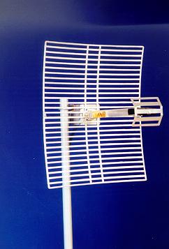
18T-2400 ANTENNA
 |
SPECIFICATIONS |
| Input Frequency |
2400-2500 MHz |
| Gain |
18dBi |
| -3 dB Beam Width |
14° |
| Front to Back Ratio |
> 23dB |
| Polarity |
Dual |
| Cross Polarity Rejection |
> 23dB |
| VSWR (Average) |
1.3:1 @ 2400-2500 MHz |
| Impedance @ Output |
50 OHMS |
| Connector "N" Type ** |
Male |
| Coaxial Pigtail - RG8** |
240 Inches |
| Input Power |
50 Watts |
Windloading
@ 100 MPH
@ 140 MPH |
39.4 lbs.
77.9 lbs. |
| Elevation Adjustment |
60° in 10° Increments |
INSTALLATION
| PACKED IN FED BOX |
PACKED IN REFLECTOR BOX |
| (1) Feed assembly |
(1) Reflector |
| (1) Sub-reflector |
(1) Mast clamp |
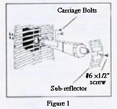
| (1) #6 ×1/2" stainless
scres |
(1) Mounting "L" shaped bracket |
| (2) Stainless 1/4 ×20×1" carriage bolts |
(1) Stainless U-bolt 1/4×20×2" |
| (2) Stainless1/4×20 Hex nuts |
(2) Stainless 1/4×20 Hex
nuts |
| (2) Stainless1/4" lock washers |
(2) Stainless 1/4" lock washers |
|
(1) Stainless flat plate washer |
|
ASSEMBLY
1. Place the sub-reflector on the front of the feed and
secure with the #6×1/2" stainless scres (Figure 1)
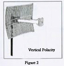
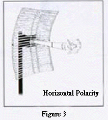
2. Determine the polarity of the antenna (Figure 2
& 3)
VERTICAL POLARITY: Refer to
(Figure 2) for proper feed alignment.
HORIZONTAL POLARITY: Refer to
(Figure 3) for proper feed alignment. |
|
|
|
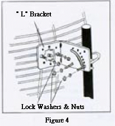
3.Place the "L"
bracket on the back of the antenna (Figure 4). Secure the feed on the front with two
carriage bolts (Figure 1). Secure the feed on the back with the lock washers and nuts
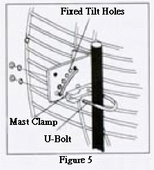
(Figure 4). 4. Place the mast clamp on the U-bolt (Figure 5).
Fasten the U-bolt on the "L" bracket with 2 lock washers and nuts (Figure 4)
Note: Fixed tilt hole provide antenna elevation up to 60° in 10°
increments (Figure 5). |
|
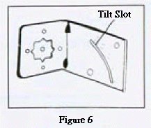
Use the flat plate washer on
the adjustable tilt slot to secure the antenna to the required elevation (Figure 6). |
|
|
|


